Monday 31 March 2014

Testing the Drawing Module: Part 1

After initial round of testing, we discovered a re-occurring crash when you tried to open a newly created page. The result of last nights work this is now fixed. For those unfamiliar, in the FreeCAD_sf_master directory run 'git pull'.

If you have any comments after testing the drawing module, please also consult this forum topic

-------------------------------------------------------

I haven't managed to do much recently. Work has snowballed and I've been having to work on a binary file converter for an Additive Manufacturing Machine. The experience from that I can imagine may be quite useful for writing and parsing other file formats if we ever need to in FreeCAD. I never would have thought I would read binary numbers as an engineer...

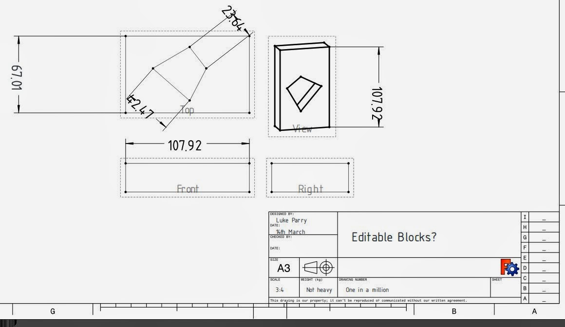
It appears there is a demand for testing the Drawing Module. It's in the stage where I any testing would be quite helpful, mainly to get feedback on the user interface and push this into the master for testing. I am aware there are some deficiencies both in missing features and bugs, but I need some motivation to finish up the GUI to make it more user friendly. Input on this would be helpful. In particular GUI mocks - hand drawings on tissue paper are accepted!

Note: Windows testers would be helpful!

 The idea of this post is to give a brief overview building FreeCAD to test out the Drawing Module.
mkdir test && cd test

The run "git clone http:://repositoryaddress" like the below to clone my Github repository into your testing directory.
git clone https://github.com/mrlukeparry/FreeCAD_sf_master.git

It should look like below. Cloning FreeCAD shouldn't take too long (it's about a 70mb download).


Ensure you have the prerequisites for compiling and building FreeCAD - consult either the wiki
or if you are really ensure ask on the forums. 

You now need to checkout out the drawing branch 
cd FreeCAD_sf_master && git checkout origin/drawing

You should now be on the drawing branch in a detached state. 


Now we create a build directory outside of the source directory and then we configure using CMake

You now need to checkout out the drawing branch 
cd ../ && mkdir build && cd build

Now we build using CMake. The options that you pass may depend on your platform or distribution. If you have problems please consult the forums. Configure the build using debug options for testing:
cmake - DCMAKE_BUILD_TYPE=Debug ../FreeCAD_sf_master


Eventually you should be configured and ready to build. All you then have to do is run make. To build faster, the option 'j' is the number of make jobs to run in parallel - set this to CPU cores + 1
make -j 7
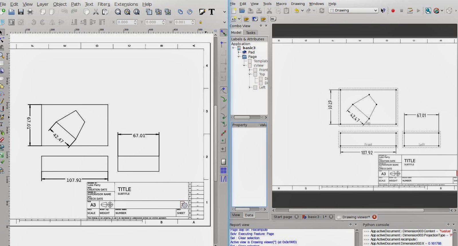
The build procedure can take between 10-30 minutes depending on your computer specification. An SSD helps considerably more so than memory. Once built you can easily test FreeCAD without having to make an installation. 

In the build directory you can simply run FreeCAD
./bin/FreeCAD

To use the Drawing Module change the workbench once you have a part.

Part 2 to follow! 

I think I will try and record a screen-cast for the next guide.

Saturday 15 March 2014

Drawing Updates

I am in the stage of trying to tidy everything up and get this baby into testing for you people to enjoy.

I noticed that the drawing performance in QGraphicsView was becoming very slow especially if you tried to zoom in. It wasn't really obvious why but through investigation I noticed that this was because of a QGraphicsItemRectangle that was being used to render the blank page background. This was even with caching enabled and redrawing seemed to persist which was the cause of the performance penalty observed.

The improvement I made was drawing the background page (a white rectangle) in the QGraphicsView drawBackground method. Instantaneously the performance was improved irrespective of zoom level. Everything comes at a price. The caveat was that we don't have a shadow for the background, but the main issue was very random segfaults. After hours of probing, it the cause was peculiar. An empty QGraphicsItemGroup was not updating its bounding box correctly. In short this got fixed with ample amounts of frustration. What is also nice is that much of the Drawing Canvas is cached so there should be little redraw slowing us down.

As a result the performance is significantly better and the user interaction on my computer is smooth.

I also was investigating the Task View created by Joe to see what can be used to create organised orthographic projections. Much of the functionality is built already in at a lower level except the automatic scaling. It's in all best interests to use code, but I am in the position where it might be easy to start with a simple interface that doesn't have all the logic embedded inside it. I'll post a topic on the forum for people's thoughts.

Through this investigation, now in a collection of Orthographic views it has an anchor view which is used to move the whole group. It already feels quite intuitive to use. This was misleadingly obvious to implement and I started off using Qt's signal and slot mechanism but this was causing a reciprocal effect, whereby movement was  exaggerated. After a few beers, I stumbled upon QGraphicsSceneMouseEvent::ignore() which allows a child items event to bubble through the child-parent hierarchy. To my surprise this work instantly and was also smooth.

Getting bored one evening, I wanted to experiment and see if we could have user-editable text fields for the SVG templates, rather than the cumbersome Property Editor. To my surprise it's quite straight forward using previous code and using the text elements in the SVG document to create QGraphicsTextTtem which can be used very easily.

Time for screenshot!


The picture above is a culmination of what's been done. The text block on the right were edited in the document. All that needs to be figured out is if people are happy with this and a mechanism for storing the data fields more intuitive than an array. 

Saturday 1 March 2014

SVG Export in Drawings

I was intending to blog last night about this, but two beers afterwards and I fell asleep - typical.

The focus now is trying to get the Drawing Module in a usable state, so that people can use it and begin testing. It's unlikely to be in the next 0.14 release, but I would definitely want to see it within the git master so that it can be test and used by the more enthusiastic users.

The remaining pieces of work are exporting the drawing. Last time, I worked on getting SVG templates working. The only issue remaining with these is that they are not automatically redrawn until you update Page properties. I also changed it so that templates provide information about the Page such as the size and orientation, so these don't have to be arbitrarily set by the user.

 I previously mentioned a while ago by using QGraphicsView we can export to a few vector formats for free. This includes PDF, Postcript and also SVG. This is only a temporary measure but is actually very useful to obtain near exact representation of the Drawing shown in the GUI. The limitation is that FreeCAD must be compiled with a GUI to get export functionality. I plan to have a separate Exporter class that will provide an interface for exporting into multiple formats.

There are a few issues with the ViewProvider classes where currently they are not very friendly with any view that isn't a Coin3D view. For the time being the only way to access the SVG export functionality is right clicking the drawing page and clicking on 'Export SVG'. There isn't a way to expose this in the FreeCAD navigation.


Export to SVG from QGraphicsView is pretty easy, it's just the case of using QSvgGenerator and passing this to QPainter and then passing this to the render method inside a QGraphicsView object (m_view)


The Drawing View class manages at a high level the QGraphicsView. The CanvasView (m_view) is the lower level and provides the higher level drawing functionality. CanvasView has two modes to toggle editing. When it is disabled it removes borders, vertices and also cosmetic lines which keep the same thickness regardless of zoom level.

The issue I was having was that the toggleEdit method wasn't working correctly. The output in the SVG file was raster for some reason. 


I knew this was a caching issue but I wasn't entirely sure where it was happening because I explicitly set this to be turned off when out of editing mode. After many hours of searching, this problem was being caused by one line. So the result is below:


 On the left is the exported Drawing opened in Inkscape. The right is the Drawing Module. 

Spot the difference: 
  • The arrow heads, which are drawn as triangles rather than SVG line end styles.
  • The SVG template losing colour for some reason.
  • The font for the dimension datum labels are different, because osifont isn't installed locally on my computer.
  • The drawn primitives within the SVG document are not grouped. 

Note: this will be a fail safe option because we don't have any control on the output at all. For example it would be useful to have groups in SVG to separate views.